Service Crossings: How to Measure Duct Trenches and Utility Crossings
A service crossing or duct run is a linear trench item measured per metre: excavation, bed and surround, the duct or pipe, warning tape, and reinstatement, with the draw pits and chambers enumerated. Measure the trench tightly and the chambers separately, and the crossing is fully billed. Measure it loosely and a service crossing becomes one of the most common causes of mid-build variations on a civils job, because the work is buried, the widths get guessed, and the draw pits get forgotten. This post walks the trench item and the combined-services case with reproducible worked examples, then the chambers.
For the wider document see a civil engineering Bill of Quantities; for the series and item structure used below, see how MMHW structures a highway item.
The trench item: measured per metre
A single-service run is a linear item. Everything in it scales with the run length, except the chambers. The example below is a 50 m low-voltage electricity duct crossing, measured to MMHW. It is the calculator default run with one change: the service type set to LV electricity (the calculator opens on a water main). Everything else resolves from the NJUG defaults: a 110 mm HDPE duct at 0.600 m cover, the NJUG minimum for LV electricity, in an auto-sized 410 mm trench. The quantities are real CivilQuants engine output, generated for this article. Treat them as a modelled example for illustration, not a tender; every number is reproducible from the same inputs.
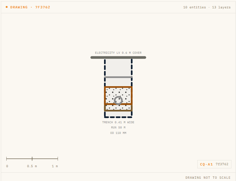
The trench section (hash 7f3762): the duct in its bed and surround, the marker tape above it, and the backfill up to the surface.
| MMHW ref | Description | Quantity | Unit |
|---|---|---|---|
| 500.4 | Excavation in trench (SHW Cl. 503) | 18.66 | m³ |
| 600.5 | Disposal of unacceptable material off-site (SHW Cl. 605) | 18.66 | m³ |
| 600.7 | Imported acceptable fill, Class 6N (SHW Cl. 601, Table 6/1) | 11.75 | m³ |
| 500.2 | Granular bedding, Class S per HA 40/01, Class 6N granular fill | 2.05 | m³ |
| 500.3 | Granular surround, Class S per HA 40/01, Class 6N granular fill | 4.86 | m³ |
| 500.9.4 | Electrical cable duct, low voltage, HDPE to BS 60100, 110 mm nominal bore, black identification, 0.600 m cover (SHW Cl. 510) | 50 | m |
| 500.10.3 | Detectable service marker tape, black (electricity LV), to NJUG 7, marked "CAUTION ELECTRICITY LV BELOW" | 50 | m |
The duct is the 50 m line, but it is only one of seven rows. The bed and surround are separate granular items (2.05 m³ and 4.86 m³), the excavation and disposal balance against them (18.66 m³ out, with 11.75 m³ of imported fill closing the column), and the warning tape is a real linear item the standard expects, colour-coded to NJUG 7. The cover depth drives everything vertical: 0.600 m of cover plus the 110 mm duct, 100 mm of bedding and 100 mm of working space below the bed gives a 0.91 m deep trench, and that depth sets the excavation. Surface reinstatement is excluded at the default, because the engine treats the pavement above the trench as its own assembly, measured separately. Bill the duct alone and you have priced a cable in mid-air.
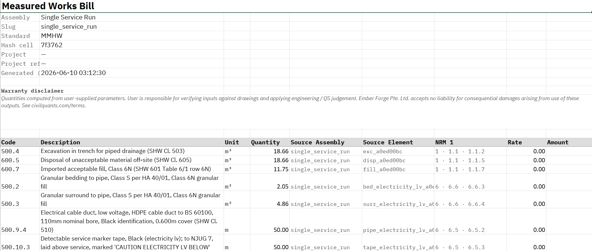
The MMHW bill (hash 7f3762): seven rows for one duct, with the bed, surround, imported fill and marker tape measured in their own right.
Single versus combined-services trench
Often several utilities share one trench, laid side by side with a clear horizontal spacing between them (typically 50 to 100 mm), each at its own cover depth: one excavation, one disposal, one backfill column, but a duct or pipe, a bed, a surround and a warning tape for each service. Below is the calculator's pre-filled three-service trench (water, gas LP and telecoms) with a fourth service added to the bundle, an LV electricity duct at its NJUG cover, over the same 50 m, measured to MMHW. The trench width is not guessed: it derives from the services themselves, the four outside diameters plus 100 mm between each pair and 150 mm clearance to each trench wall, which comes to 1.06 m here. (Rows are rounded to two decimals for reading; the export carries the full working.)
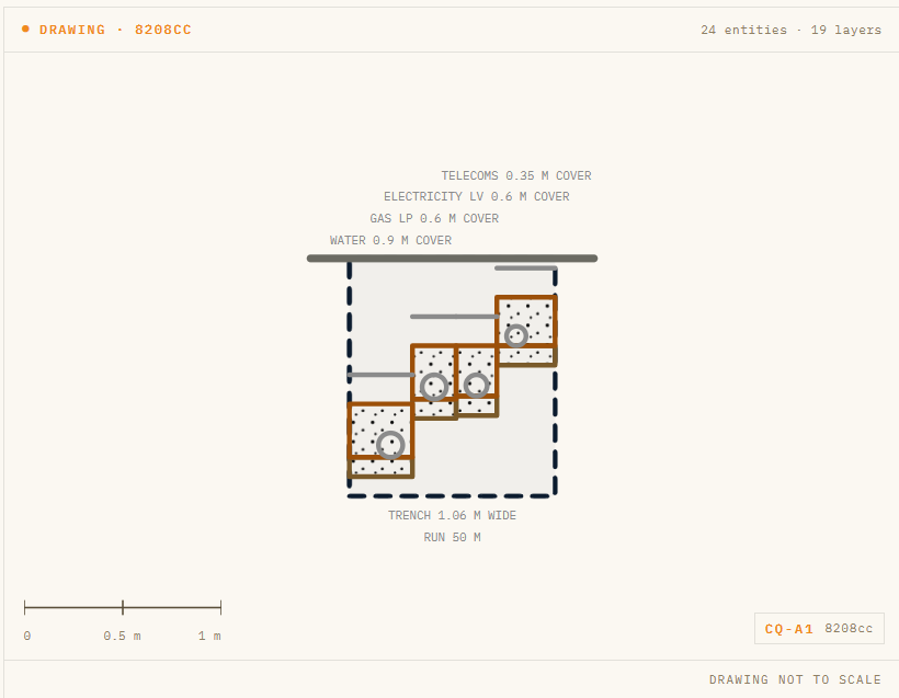
The combined trench section (hash 8208cc): four services side by side in one dig, each at its own cover depth, with the trench width derived from the services themselves.
| MMHW ref | Description | Quantity | Unit |
|---|---|---|---|
| 500.4 | Excavation in trench (SHW Cl. 503) | 64.92 | m³ |
| 600.5 | Disposal of unacceptable material off-site (SHW Cl. 605) | 64.92 | m³ |
| 600.7 | Imported acceptable fill, Class 6N (SHW Cl. 601, Table 6/1) | 47.68 | m³ |
| 500.2 | Granular bedding, Class S per HA 40/01, Class 6N granular fill | 5.29 | m³ |
| 500.3 | Granular surround, Class S per HA 40/01, Class 6N granular fill | 11.93 | m³ |
| 500.9.1 | Water service pipe, MDPE to BS 12201-2 (SDR 11), 125 mm nominal bore, 0.900 m cover (SHW Cl. 510) | 50 | m |
| 500.9.2 | Gas service pipe, low pressure, MDPE to BS EN 1555-2 (SDR 11), 125 mm nominal bore, 0.600 m cover (SHW Cl. 510) | 50 | m |
| 500.9.4 | Electrical cable duct, low voltage, HDPE to BS 60100, 110 mm nominal bore, 0.600 m cover (SHW Cl. 510) | 50 | m |
| 500.9.6 | Telecoms cable duct, uPVC to BS EN 50086, 100 mm nominal bore, 0.350 m cover (SHW Cl. 510) | 50 | m |
| 500.10.1 | Detectable service marker tape, blue (water), to NJUG 7 | 50 | m |
| 500.10.2 | Detectable service marker tape, yellow (gas LP), to NJUG 7 | 50 | m |
| 500.10.3 | Detectable service marker tape, black (electricity LV), to NJUG 7 | 50 | m |
| 500.10.4 | Detectable service marker tape, grey (telecoms), to NJUG 7 | 50 | m |
Three things to read slowly. The excavation is 64.92 m³, dug once: the deepest service (water at 0.900 m cover) sets the 1.225 m trench depth, the four services side by side set the 1.06 m width, and every shallower service sits in the same dig at its own cover (telecoms at 0.350 m, gas and LV electricity both at 0.600 m). The bed and surround are measured per service at its own lane width, the duct plus its share of the spacing, not across the full trench, so the granular total (17.2 m³) is what the gangs will actually place around four services, and the 47.68 m³ of backfill is honestly the bulk of what goes back in the hole. And the warning tape totals 200 m across four rows, one colour-coded run per service, because each utility carries its own NJUG identification.
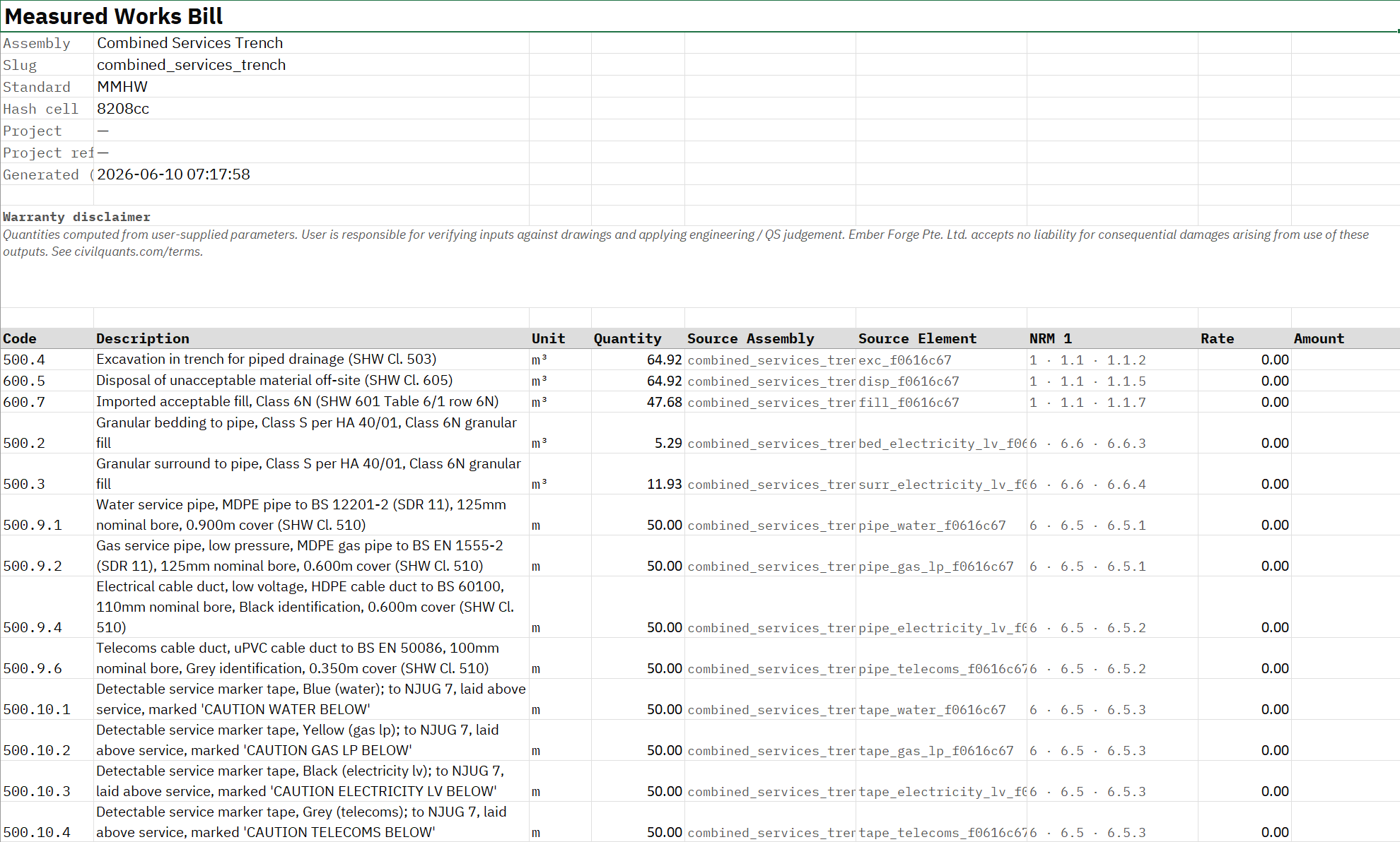
The MMHW bill (hash 8208cc): one 64.92 m³ dig shared by four services, with the bed, surround, pipe or duct and marker tape measured per service.
There is a measurement discipline hidden in that arrangement. UK practice (NJUG Volume 1) positions services apart, horizontally and in depth, so each can be maintained without disturbing its neighbours, and the engine builds that in: the trench width grows with every service you add, and a width you force below what the services physically need is rejected before it produces a bill. That is the right behaviour. A trench billed narrower than its services will be rebuilt on site as a variation, so catching it at measurement is exactly where the discipline earns its keep.
Draw pits and chambers: enumerated
Long duct runs need draw pits or jointing chambers at intervals, and these are enumerated, not linear. A draw pit is one number on the bill, but it carries its own excavation, bedding, surround and a cover-and-frame supply line, exactly like a small manhole. On a run with a draw pit every 50 m, those enumerated pits add up, and they are exactly what gets dropped when an estimator bills "200 m of duct" and stops. For the composition logic that applies to enumerated chambers, the rings, the bedding, the cover and the dig behind a single "nr", see how drainage chambers are measured.
Why tight duct measurement prevents variations
Service crossings cause more mid-build variations than almost any other item, for three reasons. The work is buried, so an under-measured trench is not visible until it is dug. The trench width for multiple services is routinely guessed, and a 1.0 m trench billed at 0.7 m under-measures every volume row by nearly a third: dig, bed, surround and backfill together. Deriving the width from the services, their diameters plus the spacing between them, removes the guess. And the draw pits get forgotten, because they are enumerated items hiding in a linear job. Measuring the trench to its real width, with the chambers counted and the reinstatement matched to the surface above, removes the three biggest sources of the variation account.
Doing it faster
A duct run looks like one line and bills like a dozen: the duct, its bed, its surround, the excavation and disposal that balance them, the colour-coded warning tape, and the enumerated draw pits. A parametric approach returns the whole trench from the service type, cover and length, with the trench width derived from the services and the bed and surround sized to each service's lane before a bill is produced. The examples above are real engine output, reproducible from the same inputs, measured in accordance with MMHW. It is a tool for the estimator, not a replacement for one: a modelled example for illustration, not a tender.
Common errors
- Wrong trench width for multiple services. A combined trench is wider than a single run. Guess the width and every volume row is wrong by the same fraction.
- Forgetting the draw pits. They are enumerated items in a linear job, so they fall off the bill. Count them per run.
- Missing reinstatement. The trench has to be reinstated to match whatever is above it (carriageway, footway or verge), and that reinstatement is its own item, measured separately from the trench.
- Squeezing the services together. Services share a trench side by side with a real clear spacing between them (50 to 100 mm) and each at its own NJUG cover. Bill a trench too narrow for that arrangement and it will be rebuilt on site.
FAQ
How are duct trenches measured in a BoQ? As a linear item per metre: excavation, granular bed and surround, the duct or pipe, colour-coded warning tape, and reinstatement, with any draw pits or chambers enumerated separately.
How do you measure a combined-services trench? As one excavation, one disposal and one backfill column, with a duct or pipe, a bed, a surround and a warning tape for each service at its own cover depth. The excavation depth is set by the deepest service.
Are draw pits measured separately? Yes. Draw pits and jointing chambers are enumerated items (by number), each carrying its own excavation, surround and cover-and-frame supply, even though the run they sit on is linear.
What is included in a duct trench rate? The standard deems certain incidental work into the trench rate, but the bed, surround, imported fill, disposal and warning tape are measured items in their own right, not bundled into the duct line.
How is reinstatement measured? Matched to the surface above the trench (carriageway, footway or verge), as its own item. Reinstatement to a trafficked carriageway is a different, dearer item from reinstatement to a verge.
Why do service crossings cause so many variations? Because the work is buried, the trench width is routinely under-measured, and the enumerated draw pits get forgotten. Tight measurement of width, chambers and reinstatement removes the three biggest sources of the variation account.
Try it
Measure a service run from its type, cover and length and read the full trench bill. Single service run is a paid assembly, so the worked standards (MMHW, CESMM4, NRM2, SMM7) need a pass or subscription. Start a 7-day pass for £15, or try a free assembly to MMHW with no sign-up, then build the trench on the single service run calculator.
Frequently asked questions
- How are duct trenches measured in a BoQ?
- As a linear item per metre: excavation, granular bed and surround, the duct or pipe, colour-coded warning tape, and reinstatement, with any draw pits or chambers enumerated separately.
- How do you measure a combined-services trench?
- As one excavation, one disposal and one backfill column, with a duct or pipe, a bed, a surround and a warning tape for each service at its own cover depth. The excavation depth is set by the deepest service.
- Are draw pits measured separately?
- Yes. Draw pits and jointing chambers are enumerated items (by number), each carrying its own excavation, surround and cover-and-frame supply, even though the run they sit on is linear.
- What is included in a duct trench rate?
- The standard deems certain incidental work into the trench rate, but the bed, surround, imported fill, disposal and warning tape are measured items in their own right, not bundled into the duct line.
- How is reinstatement measured?
- Matched to the surface above the trench (carriageway, footway or verge), as its own item. Reinstatement to a trafficked carriageway is a different, dearer item from reinstatement to a verge.
- Why do service crossings cause so many variations?
- Because the work is buried, the trench width is routinely under-measured, and the enumerated draw pits get forgotten. Tight measurement of width, chambers and reinstatement removes the three biggest sources of the variation account.